How To: P0342 (Cam Position No Signal)

N/A tech, Cold Air Intakes, Spark Plugs/wires, Cat backs, Exhaust...etc

Moderators: daewoomofo, Moderators Group

Locked
Trey05Woo
Super
Posts: 230
Joined: Sat Aug 08, 2009 6:07 pm
Location: Miami, Fl

How To: P0342 (Cam Position No Signal)

Post by Trey05Woo »

Sup board. It has been a long while since I been on. I was the on the tail-end of my studies, just swamped with little time for anything. I finally graduated in December, and things have normalized (some) now. Also my Lanos, I gifted to my GF's sister who is now studying in upstate Florida and she took the car up there. It came back down with a ton of problems, and 90K miles! But that is the fun part now, getting it back to the way it was when I handed it to her, and documenting all these repairs, and passing it on to you all, so you can apply them to your own personal repairs. In this thread I will address:

P0342 Cam Signal Fault

Explain how the sensor works and what it does

Explain the components that make up the system, and common problem areas

Explain the common symptoms associated with a system that is not operating per spec

Explain how to diagnose the system, and isolate the problem.

Tools needed for the repair.

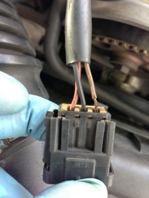
CAM POSITION SENSOR The sensor is a simple hall effect sensor mounted in-between the intake and exhaust cam shaft sprockets. The sensor provides the ECM (engine computer) with a signal so the ECM can identify the position of each intake valve (open or closed), so that it may fire each respective injector on the intake stroke. This is called Sequential Fuel Injection, and the CMP (cam position sensor) is a detrimental component required for correct system operation. The sensor communicates with the ECM through it's three prong connector which contains 3 wires, and this is basically the make up of the entire system. Before just replacing a part you should make sure the other components are ok, and the wiring between them. In this case the CMP, the ECM, and the wiring between the two. The CMP connector is a common trouble area. It is plastic and gets brittle with age, and tends to break off the locks located on each side. This causes a loose connection due to engine vibration during operation, causing an intermittent fault, and a CEL with a respective trouble code. The wiring is also a common problem area. The insulation tends to become hard and brittle with age, and flake off. This is called Chafing in the automotive industry, and causes all kinds of crazy intermittent faults, and false diagnosis. If you see below, my vehicle suffers from both, a broken lock, AND wire chafing on the 5 Volt reference signal. THIS MUST BE ADDRESSED...
Image

Notice the wires, and the one all on the right how it is exposed, and looks weathered and beat up. While it is not broken, and my signals were all to spec, I'm still going to repair the connector to prevent future problems.
Wire definitions (left ot right):
Red/White (Battery +)
Black (system ground)
Brown/White (Cam signal/5volt reference)

What happens when P0342 sets:

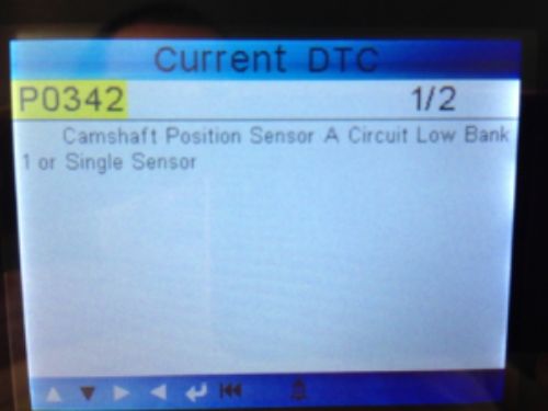
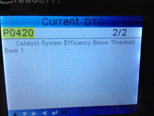
The computer lights the CEL, ignores the cam single, and fires the injectors based on a fixed algorithm it references using the crank position sensor. This causes a richer than normal mixture in the engine which in turn affects the performance and efficiency of your engine. You can expect a higher than normal fuel consumption, a rough, or lumpy idle, rich smell from the exhaust, sluggish low speed performance, and affected catalyst performance. Usually P0342 will cause catalyst, as well as fuel related DTC's to set conjointly. Also extended neglect can cause permanent damage to your catalyst, as it is not designed to handle extended rich mixtures in the exhaust. My car set both 0342/and 420 see below.
Image
Image

Since we know that the CMP is detrimental in controlling the fuel mixture being fed into the engine, and we know if a problem with the circuit presents itself, the engine will run richer, we shall focus our attention on P0342 for the moment, because there is a high chance that correcting the issue, will correct the P0420 as well.

Next post testing the system voltage/signal voltage....
Specializing in European & Korean Only
Doral Auto Care
5171 NW 36th
Virginia Gardens, FL 33166
(305) 871-1121

BS Mechanical Engineering 12/12 (FINALLY!)

ASE Certified:
Engine Electrical
Engine Performance/Advance
Brakes & ABS
Air Conditioning
Trey05Woo
Super
Posts: 230
Joined: Sat Aug 08, 2009 6:07 pm
Location: Miami, Fl

Re: How To: P0342 (Cam Position No Signal)

Post by Trey05Woo »

You will need some tools to properly diagnose and fix the problem they are listed below:

Voltmeter & test lead adaptors, or spare wire
10mm low profile socket or universal socket (preferred)
flat head screw driver or 1/4" socket
Ratchet and an extension for sockets
T-15 Torx bit socket, or key, or driver

Your first step should be to remove the ignition wire cover from the top of the valve cover. This is held in place by some T15 bolts, and on some models by 10mm plastic cap nuts. This gives you access to the CMP connector. Disconnect it and pay attention to its physical condition. Is it missing locks, broken, or otherwise not creating a firm clean connection at the sensor? Are any of the wires chafed or cracked? If so, you should address this first, prior to replacing any components in the system.

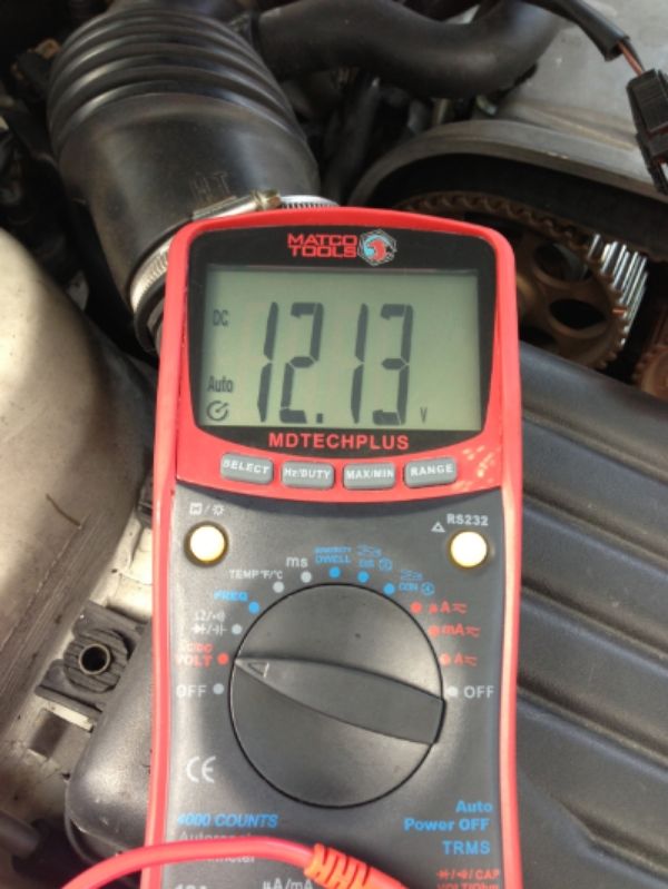
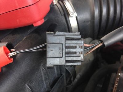
Checking the power and ground circuits, and the ECM 5 volt reference signal. This is done with the Key ON engine OFF. With the CMP connetor in your hands, back probe the Red/wht and Blk wires. Set your volt meter to read volts, and you should see 12v like below.

Image

As you can see I used plain 18 gauge wire, and my test lead adapters to prevent damage to the terminals. Below my voltmeter reflects the spec voltage:

Image

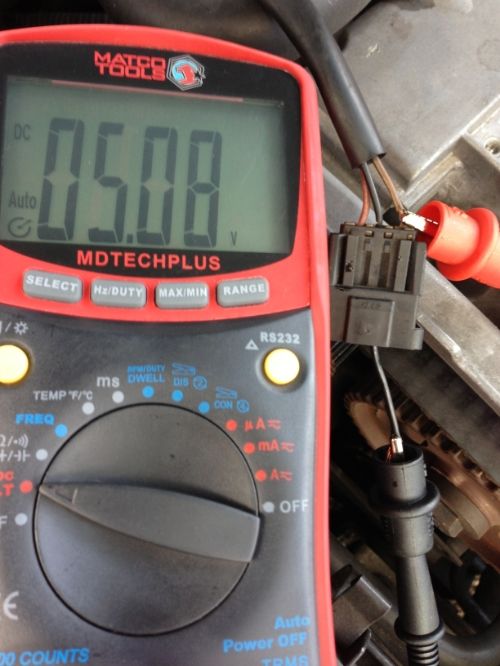
We have now confirmed that both the power and ground feed of the sensor are ok. The sensor still needs the 5 volt reference to properly communicate with the ECM. This is checked as so: take your leads and relocate the red read to the brown/white wire terminal, and leave your black lead on the black wire terminal of the connector. This would be the wire in the middle. As you can see, my wire is so chafed, I was able to put my adapter right on the wire itself! Incredibly however, my signal was clean and strong. See below. You should be at or very close to 5.0v

Image

We have now confirmed that we have power, ground, and 5 volt reference voltage. This confirms the ECM is working to spec, the wiring is ok, and that can only leave one culprit. The CMP. Looks like my car needs a new CMP sensor. I want to emphasize that you want to wiggle, and play with the wiring as you check the readings for no sudden drops, or spikes, in the readings. if you get these, then there is a wiring problem some where in the harness.

Finally we can also check for the CMP signal to the ECM itself. This has to be done with the sensor connected, and the engine running. Since my wire was so chafed, I was able to leave the red lead connected, and ran ground from the battery directly. I am positive of the readings, because I confirmed the connector ground is known and good. I replaced the sensor, and confirmed the new one was working. I'll add it in the next post, along with instructions on how to replace the sensor itself.
Specializing in European & Korean Only
Doral Auto Care
5171 NW 36th
Virginia Gardens, FL 33166
(305) 871-1121

BS Mechanical Engineering 12/12 (FINALLY!)

ASE Certified:
Engine Electrical
Engine Performance/Advance
Brakes & ABS
Air Conditioning
Trey05Woo
Super
Posts: 230
Joined: Sat Aug 08, 2009 6:07 pm
Location: Miami, Fl

Re: How To: P0342 (Cam Position No Signal)

Post by Trey05Woo »

You can check your CMP signal by running the following test: Reconnect the sensor to it's connector. Back-probe the Brown/White Ref signal wire with your RED lead, and either run your BLACK lead to battery ground, engine, or back-probe the black wire of the connector. Start the engine and pay attention to the readings. You should get an even smooth fluctuation at idle with no DROP OFF. You should not see 0 volts, and you should not see anything above 6 volts @ idle. If you accelerate the engine, you will see high voltage fluctuation, it should NEVER DROP TO 0 VOLTS. See my video link below..


http://s209.photobucket.com/user/G_Vela ... g.mp4.html

I actually ran the above test with the old sensor, and saw no change in voltage. Indicating my sensor was just completely inop. Made sense, because if I cleared the check engine light, it almost returned immediately. Below are the instructions to replace the CMP...


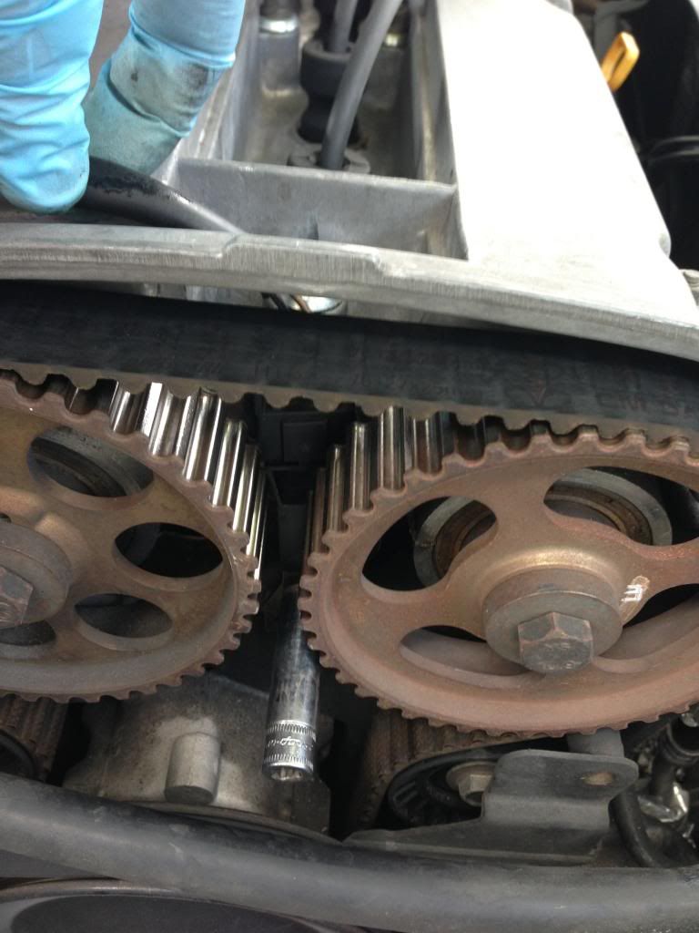
By now you should already have removed, the ignition wire cover. So continue by removing the air box, and the front upper timing cover. You will need a 10mm socket, extention, and ratchet. You will also either need a flat head screwdriver for the clamps of the airbox mufflers, or a 1/4 SAE socket. Reconnect the CMP and leave it connected. This will help you in removing, and then installing the new one. Should look like below:

Image

Notice how I am using my left hand to hold the sensor using it's harness, and I am using a low profile socket to remove the two bolts holding the sensor in place. This particular socket is a Snap On low profile 1/4 drive socket with magnetic tip. It works wonders because the two 10mm bolts are extremely small and you do not want them to fall, as they typically fall inside the lower cover, and this means removing it to prevent any damage to the timing components. If you do not have a magnetic socket, use a magnet and be ready to catch the screws as they come loose. Once you remove the screws, pull the sensor straight up and remove it from it's connector. Install the new one onto the connector/harness, and relocate it in place. Use your hand to hold the sensor in place, and CAREFULLY re-install the bolts. Making sure they do not fall inside the lower cover. They do not need to be tight. Hand torque will suffice. Re-install the upper timing cover, ignition cover, and air box, and you are set. You may want to confirm the new sensor is working before re-installing all the accessories.

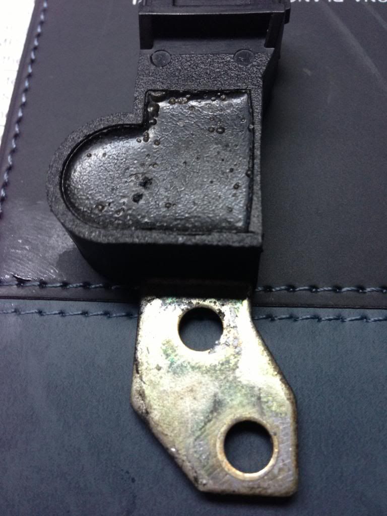
Here is a pic of my old sensor. As you can see it failed due to age, and temperature exposure. The hard insulation is bubbled up and sticky. No doubt this has caused an internal short in the sensor itself. I'm going to tear it apart and find the issue.

Image

Hopefully this post cleared up the frequent P0342 and how to repair it. I replaced the connector, and the chafed wire as well, because even though my signals were surprisingly clean, and solid, I know from experience this will cause problems down the road. I will post those pics soon as I get a chance.
Specializing in European & Korean Only
Doral Auto Care
5171 NW 36th
Virginia Gardens, FL 33166
(305) 871-1121

BS Mechanical Engineering 12/12 (FINALLY!)

ASE Certified:
Engine Electrical
Engine Performance/Advance
Brakes & ABS
Air Conditioning
Puddle31
Super
Posts: 285
Joined: Thu Feb 05, 2009 6:40 pm

Re: How To: P0342 (Cam Position No Signal)

Post by Puddle31 »

nice job, you did everything but repair it for me!
Trey05Woo
Super
Posts: 230
Joined: Sat Aug 08, 2009 6:07 pm
Location: Miami, Fl

Re: How To: P0342 (Cam Position No Signal)

Post by Trey05Woo »

NP... You had a connection issue I assume? I've changed more harnesses and connectors, than the sensors themselves in all my experiences with the 1.6 and 2.x liter engines.
Specializing in European & Korean Only
Doral Auto Care
5171 NW 36th
Virginia Gardens, FL 33166
(305) 871-1121

BS Mechanical Engineering 12/12 (FINALLY!)

ASE Certified:
Engine Electrical
Engine Performance/Advance
Brakes & ABS
Air Conditioning
Puddle31
Super
Posts: 285
Joined: Thu Feb 05, 2009 6:40 pm

Re: How To: P0342 (Cam Position No Signal)

Post by Puddle31 »

when i had my sensor problem, a replacement sensor solved it. Don't know if it was a bad sensor or just a bad connection. I had to get it fixed to pass inspection.
Locked